Shakshat Virtual Lab 
INDIAN INSTITUTE OF TECHNOLOGY GUWAHATI
Theory:
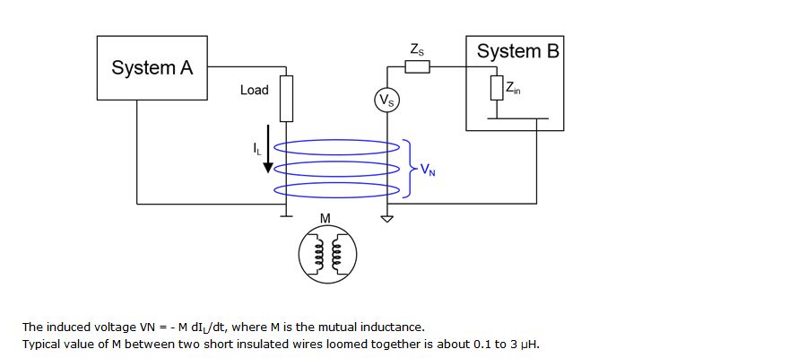
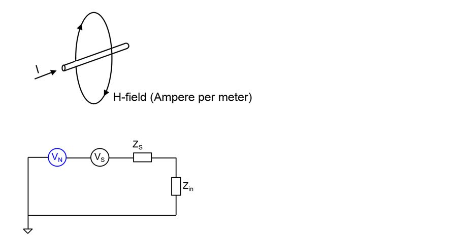
The circuit below gives us basic idea of how interference is coupled magnetically to a system. The System A generates a variable output which passes through the load. This signal passes through a portion of the circuit that is parallel to a circuit that supplies the input to System B. As we know, a current flowing through a conductor creates a magnetic field surrounding it. Thus, this field is coupled to the second circuit essentially behaving like two parallel inductors. This coupled magnetic field induces a voltage in series with the supply voltage VS which is given as input to System B. This results in the output of System B to consist of unwanted components in addition to the actual output. This effect is greater when the two circuits are closer and reduces as the distance between them increases. The amount of noise also depends on the frequency and amplitude of the current IL.
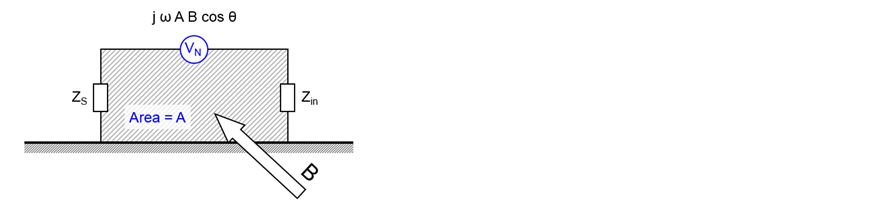
Sinusoidal magnetic field of flux density B and frequency ω will induce VN with magnitude of j ω A B cos θ, where A is the area of the loop and B cuts area at an angle of θ.
To minimize magnetic field coupling
1. Keep loop area minimum Orient
2. loop to have θ 90 deg